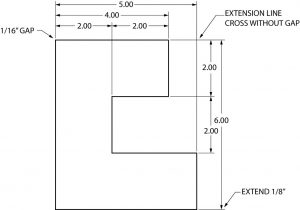
DIMENSIONING The dimension line should be approximately 3/8” from
4.8 (689) In stock
Notation Errors For fractional inches there is no leading zero before the decimal point. As an example, a quarter of an inch becomes .25 and not Avoid inserting a closed quotation mark for an inch measurement such as .25”, and using the notation of “mm” for millimeter measurements such as 68mm.
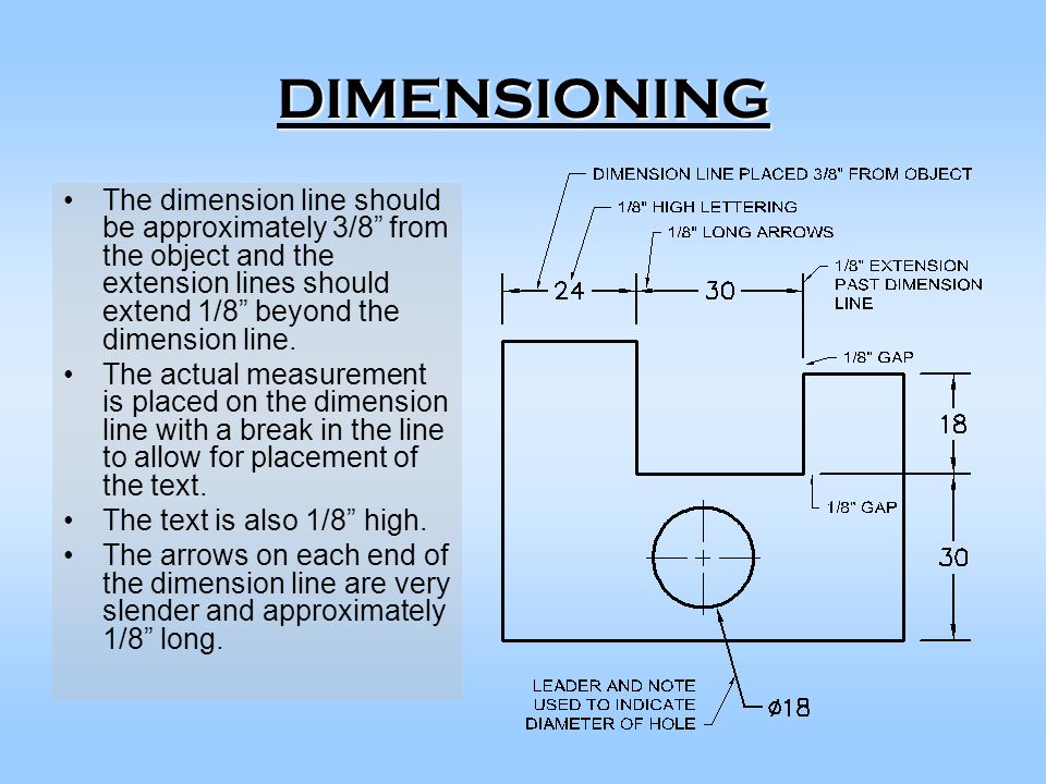
DIMENSIONING The dimension line should be approximately 3/8” from the object and the extension lines should extend 1/8” beyond the dimension line. The.
The actual measurement is placed on the dimension line with a break in the line to allow for placement of the text. The text is also 1/8 high. The arrows on each end of the dimension line are very slender and approximately 1/8 long.
For fractional inches there is no leading zero before the decimal point. As an example, a quarter of an inch becomes .25 and not Avoid inserting a closed quotation mark for an inch measurement such as .25 , and using the notation of mm for millimeter measurements such as 68mm.
Continuous dimensioning starts on one edge of an object and continues across the object. Unless the object has a finished surface, the dimensions can start on either end or the top or bottom. Omit one dimension in a series since the overall dimension will provide the missing measurement.
Always place dimensions where the shape is most clearly visible. The cuts are more easily seen in the front view. The corners of the cuts in the front view also appear to be formed with L’s where lines intersect. The same cuts, when projected to the top view, appear to form corner intersections with T’s . In order to determine the most visible view, always dimension to the L’s and not the T’s .
Hidden Lines Never dimension to a hidden line unless a peculiarity of the object forces the location of an extension line on a hidden line.
Angles For an angled surface, use either two coordinates or an angle and one coordinate.
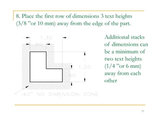
In order to logically place dimensions, approach the object with the intent of dimensioning in the order of size, location and overall dimensions. Size dimensions - Start with the smaller parts of the object and work toward the larger and finally the overall dimensions.
For very small dimensions, the arrows and text are placed outside the extension lines. As room permits, text is placed between the extension lines and finally the text and arrows. The last illustration shows a series of small measurements where the interior arrows are omitted.
For small arcs, omit the center mark and place the arrow and text on the outside of the curve. As the radius increases, the arrow moves inside the curve and the radius is noted with a leader. When the radius is large enough, the measurement also moves inside the curve.
The hole is dimensioned where it appears round or circular. The arrow attached to the leader touches the outside of the circle and points to the center of the hole. Note that the measurement is a diameter by using the symbol of the circle with a slash.
The cylinder is dimensioned where it appears rectangular. Since the cylinder is a complete circle, always provide the diameter and never the radius. Note that the measurement is a diameter by using the symbol of the circle with a slash.
Locate the rectangular prism in the top view where two dimensions (height and width) can be used. Notice that the position of the rectangular prism is more clearly visible in the top view.
Location dimensions for circular features such as holes and cylinders are always placed on the object where the hole or cylinder appears round (circular) and not in the view where the hole appears as hidden lines.
The finished surface is important while dimensioning as the linear dimensions typically begin from the finished surface. The finished surface is noted by the finished surface mark ( V ) appearing where the finished surface appears as an edge view.
a. Center points on the longitudinal axis are located and the radii are indicated with a note. b. Linear measurements indicate the overall size of the slot and the radii are specified. c. A note indicates the two linear dimensions of the slot and another note specifies the radii. Choose the most appropriate technique for sizing the slotted hole. The technique used for sizing the slot determines how the slot is located.
Holes or cylinders can be located by referencing the diameter of the circle or the radius of the arc. This technique is known as a circle of centers or bolt circle because the holes would typically allow for a bolt to pass through and fasten this part to another. Slotted holes can be dimensioned several different ways. a. Center points on the longitudinal axis are located and the radii are indicated with a note. b. Linear measurements indicate the overall size of the slot and the radii are specified. c. A note indicates the two linear dimensions of the slot and another note specifies the radii.
After the size and location dimensions have been positioned on the object and necessary notes have been added, the overall dimensions are placed. The overall dimensions provide the overall height, width, and depth for the object. They are typically placed between the views of the object. Avoid indicating each of the overall dimensions more than once.
Avoid giving an overall measurement for the rounded-end object since a combination of the location dimension and the radius (rounded end) or diameter (cylindrical feature) provides the overall dimension.
The first technique is to provide the location dimension between the center points. The measurements of the radii are given in a note. Omit the overall dimension as location dimension and the radii provide the overall measurement. The second technique is to provide overall dimensions in the view where the rounded ends appear circular. Since the overall size has been given, the radii are noted with only the R to indicate that the ends are formed with a constant radius.

Dimensioning Standards - ppt download
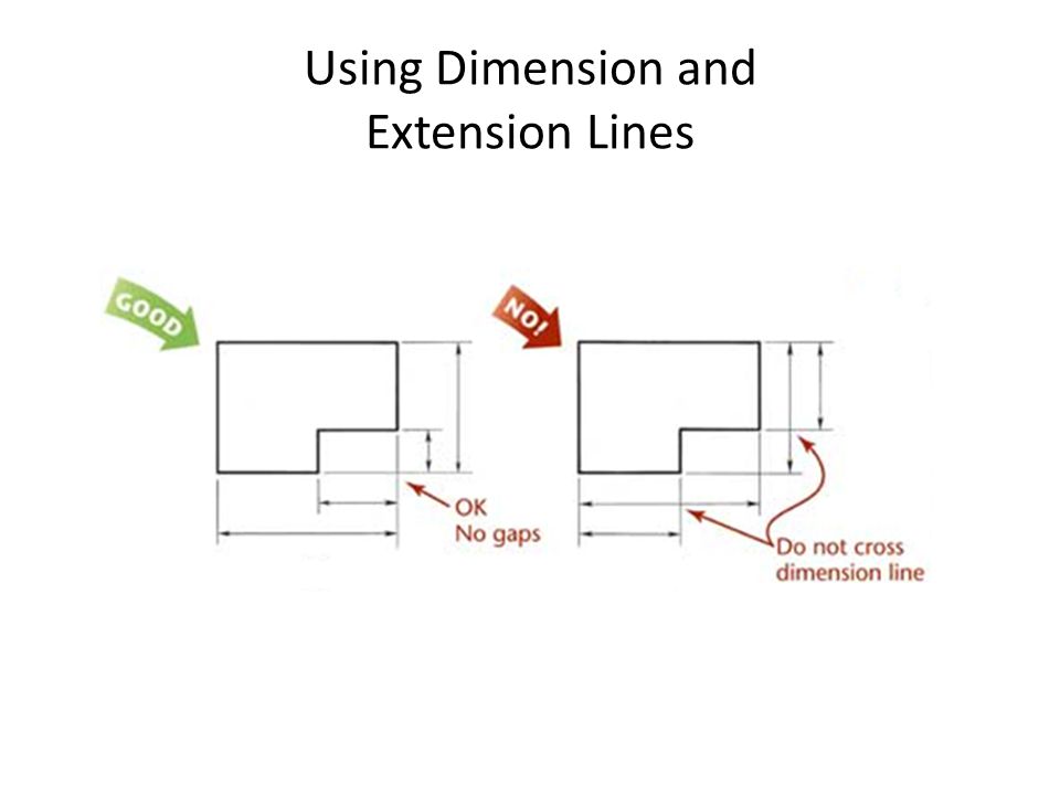
Dimensioning do's and don't

Correction on the Roorkee Chair in 'Campaign Furniture' – Lost Art
BASIC DIMENSIONING RULES - ppt download
Why Post Frame Wall Girts Overhang Posts - Hansen Buildings

CE En 112 Engineering Drawing with CAD Application - ppt video online download
Dimensioning – Basic Blueprint Reading
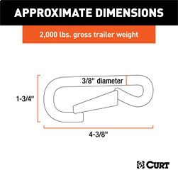
Trailer Hitch Safety Chain Hook - CURT 81266
Dimensioning Chapter ppt video online download

Unit 4 Extension Lines And Dimension Lines - ppt video online download
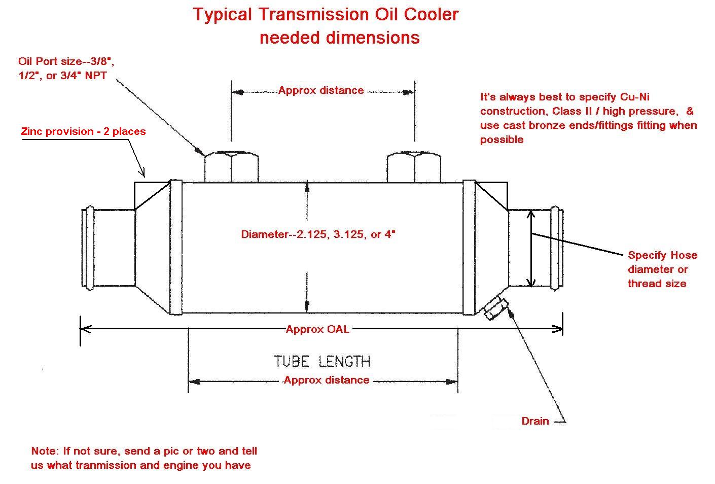
How to Measure a Gear / Transmission Oil Cooler - Seaboard Marine
Learning Objectives Define the following: Dimension line, Extension line, Reference dimension, and Leader Be able to understand the basic rules of dimensioning. - ppt video online download

Class 14 presentation

DIMENSIONING The dimension line should be approximately 3/8” from
PPT - Dimensioning (WEEK 2) PowerPoint Presentation, free download
How to draw Dimension and Extension Lines in Mechanical Drawing
Five Flute - Engineering design review platform for modern
AutoCAD 2024 Help, About Fitting Dimension Text Within Extension Lines
- Manfrotto PRO Light Multiloader Camera Backpack M for DSLR and
- Zoom Horny Toad
 Baseball Cap Surf Hair Don'T Care Ocean Haircut Dad Hats for Men & Women 1 Size
 wikiwiki 9ft Outdoor Patio Table Umbrella, Sturdy
 VINTAGE Heddon Lucky 13 Red Head Shiner 3 3/4Tack Eye WoodTopwater/Surface Lure
 P-Line Floroclear Clear Fishing Line (Filler Spool) : : Sports, Fitness & Outdoors
))/1109180.json?$Prod_PLPThumb$)